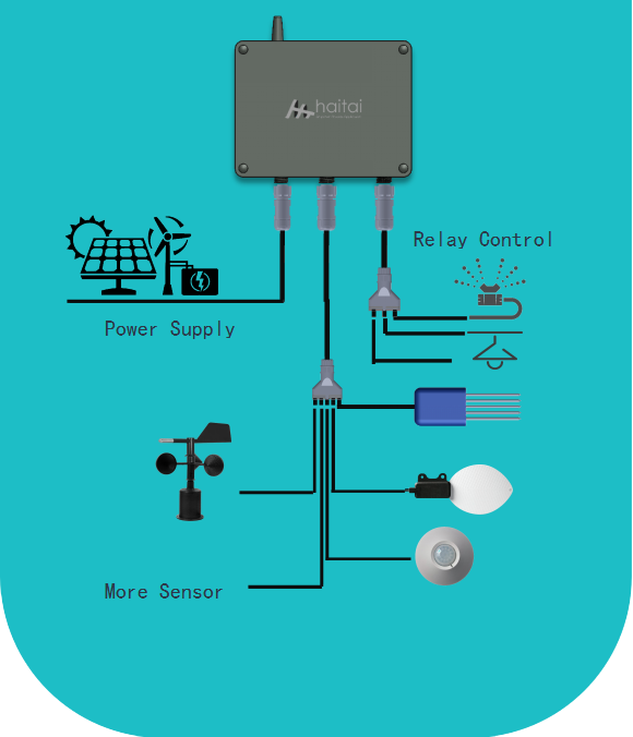
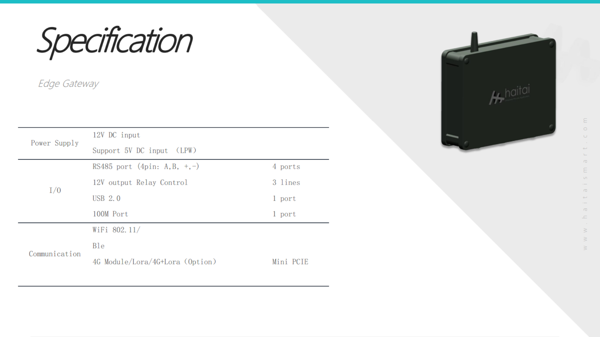
This edge controller acquires sensor data and controls devices. It includes:
- 4 × RS-485 ports for Modbus/RTU sensors/devices
- 3 × 12 V relay outputs for switching pumps, valves, fans, etc.
- Local data logging and edge processing; optional cloud forwarding
Safety
- Power off before wiring.
- Use proper isolation for RS-485 lines and relay loads.
- Ensure relay loads do not exceed rated current/voltage.
- Follow local electrical codes.
Connections
- Power
- Connect 12 V DC supply to the controller’s power input (observe polarity).
- Verify supply can handle controller + relay total current.
- RS-485 (4 ports)
- Each port has A(+)/B(−) differential pair and ground.
- Use twisted-pair cable, terminate 120 Ω at both ends when needed.
- Set unique Modbus addresses/IDs for each connected device.
- Configure baud rate/parity/stop bits to match devices.
- Relays (3 × 12 V)
- Relay coil driven by controller at 12 V; outputs are typically SPDT or NO/NC—check device spec.
- Wire switched load to relay common and NO/NC depending on required behavior.
- Protect inductive loads with flyback diodes or external suppression if necessary.
- Sensors / I/O
- Connect sensor power and signal lines per their specs.
- Use shielded cable for analog/low-voltage signals and tie shield to ground at one end.
Configuration
- Network / Serial Settings
- Access controller UI (web/serial/desktop app) or use provided configuration tool.
- Configure each RS-485 port: protocol (Modbus RTU), baud rate, parity, IDs, timeout.
- Map Inputs to Functions
- Create data acquisition channels mapping Modbus registers to named variables.
- Set sampling interval and smoothing/averaging if available.
- Relay Logic
- Define control rules: threshold-based (e.g., soil moisture < X → relay ON), schedule, or remote commands.
- Configure hysteresis and minimum on/off times to prevent chattering.
- Logging & Forwarding
- Enable local logging and set retention.
- Configure cloud/MQTT/HTTP endpoints and credentials for remote telemetry.
Maintenance & Troubleshooting
Keep firmware updated per vendor instructions.
Verify LED indicators: power, COM activity, relay state.
If RS-485 comms fail: check wiring polarity, termination, ground reference, and device IDs.
If relay not switching: verify 12 V power, controller relay enable, and load wiring.